


Introduction to PETG Blow Molding
What is PETG?
PETG (Polyethylene Terephthalate Glycol) is a type of thermoplastic polyester, known for its excellent clarity, ...
Content
- 1 What Is a 2L–10L Bottle Blow Molding Machine?
- 2 Core Machine Configurations for the 2L–10L Range
- 3 Key Technical Specifications to Evaluate
- 4 Compatible Materials and Their Processing Characteristics
- 5 Output Rates and Productivity Benchmarks
- 6 Mold Design Considerations for 2L–10L Containers
- 7 Quality Control and Testing Requirements
What Is a 2L–10L Bottle Blow Molding Machine?
A 2L–10L bottle blow molding machine is a category of industrial equipment designed specifically to produce medium-to-large hollow plastic containers ranging from 2 liters up to 10 liters in capacity. These machines are used to manufacture products such as motor oil bottles, household chemical containers, water jugs, detergent bottles, industrial solvent containers, agricultural chemical jugs, and food-grade buckets. The volume range of 2L to 10L sits between the high-speed small-bottle sector (below 2L) and the heavy-duty industrial drum sector (above 10L), making these machines a versatile platform for a wide range of packaging applications that demand robust container walls, precise neck finishes, and consistent dimensional accuracy across large production runs.
The dominant process technology used in this size range is extrusion blow molding (EBM), in which a molten plastic tube called a parison is extruded downward between open mold halves, the mold closes around the parison, and compressed air inflates the parison against the mold cavity walls to form the bottle shape. Injection stretch blow molding (ISBM) is used for some PET containers in the lower end of this range, but EBM with HDPE, LDPE, PP, or co-extruded multi-layer materials dominates production at 2L and above due to its flexibility in handling complex shapes, handles, and thick-walled containers.
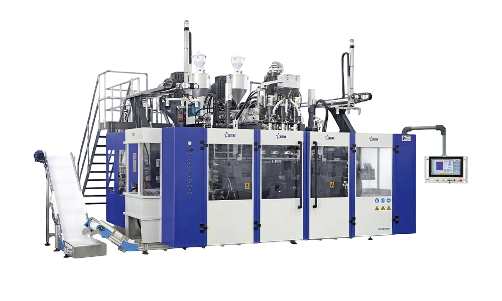
Core Machine Configurations for the 2L–10L Range
Machines in the 2L–10L category are available in several mechanical configurations, each suited to different production volumes, bottle geometries, and automation levels. Selecting the right configuration requires matching the machine's output rate, mold capacity, and material handling system to the specific production demands of the application.
Single-Station Shuttle Machines
Single-station shuttle blow molding machines use one or two mold carriages mounted on a linear shuttle system that moves laterally beneath a fixed extrusion head. The parison is extruded, the mold closes and shuttles to a blow station where the bottle is inflated and cooled, and the mold then returns to the extrusion position for the next cycle. This configuration is well suited to large bottles in the 5L–10L range where long cooling times make multi-station designs less efficient, and where the tooling cost per cavity is high. Shuttle machines typically run one to four cavities per station and are preferred for thick-walled containers, handled jugs, and specialty shapes that require extended cooling dwell time.
Rotary Wheel Machines
Rotary wheel blow molding machines carry multiple mold stations arranged around a continuously rotating wheel. As the wheel rotates, each mold station passes the extrusion head to receive a parison, then moves through an arc where the bottle is blown, cooled, and ejected before returning to the extrusion position. Rotary machines are highly productive for medium-volume containers in the 2L–5L range, where cycle times are short enough to benefit from the continuous motion of the wheel. They require higher capital investment than shuttle machines but deliver significantly higher output per unit of floor space and per unit of energy consumed.
Accumulator Head Machines
For bottles at the upper end of the 2L–10L range — particularly those requiring large parisons with precise wall thickness distribution — accumulator head machines store a charge of molten resin in a hydraulic accumulator cylinder and then rapidly inject the full parison shot in a fraction of a second. This rapid parison drop minimizes sagging and ensures consistent wall thickness distribution in tall, large-diameter containers where a slow continuous extrusion would produce unacceptable taper due to the parison's own weight. Accumulator head machines are the standard choice for 8L–10L handled containers, 10L jerricans, and containers made from engineering resins with narrow processing windows.
Key Technical Specifications to Evaluate
When specifying or comparing 2L–10L blow molding machines, several technical parameters directly determine whether a machine will meet production requirements for a given container and resin combination. Understanding these parameters prevents costly mismatches between machine capability and production targets.
- Extruder screw diameter and L/D ratio: The extruder screw plasticizes and pumps molten resin to the die head. For the 2L–10L range, screw diameters of 60 mm to 120 mm are typical, with L/D ratios of 24:1 to 30:1. A longer L/D ratio provides more residence time for thorough melting and homogenization, which is especially important when processing regrind-containing blends or materials with narrow melt temperature windows such as HMWHDPE used in chemical containers.
- Die head and parison programming: The die head controls the annular gap through which the parison is extruded. Parison programmers (typically 100-point or 256-point electronic controllers) vary the die gap dynamically as the parison is extruded, thickening the wall in areas that will be stretched thin during blowing and thinning it where minimal stretching occurs. Precise parison programming is essential for containers with handles, offset necks, or complex tapered shapes in the 5L–10L range where uneven wall distribution would cause structural failures or excessive material use.
- Clamping force: The mold clamping unit must generate sufficient force to keep the mold halves closed against the internal blow pressure without flash leakage at the parting line. For 2L–10L containers blown at typical pressures of 6–10 bar, clamping forces of 30 kN to 150 kN are common depending on the projected mold area. Insufficient clamping force produces flash at the parting line, increasing trim scrap and potentially compromising container integrity.
- Blow air system: Blow air pressure, flow rate, and cooling air volume directly determine cycle time and bottle wall quality. High-volume low-pressure blowing followed by high-pressure lock-up is standard for large containers. Internal cooling with chilled air or liquid nitrogen injection can reduce cooling time by 20–40% for thick-walled 8L–10L containers, significantly improving output rate.
- Deflashing and downstream automation: Containers in this size range typically have significant top and bottom flash that must be trimmed before packaging. Integrated deflashing units — either rotary trimming heads or punch-and-die trim presses — mounted inline downstream of the blow station eliminate the need for manual trimming, reduce labor cost, and improve dimensional consistency of the finished neck and base.
Compatible Materials and Their Processing Characteristics
The 2L–10L blow molding sector processes a wider range of materials than small-bottle applications because the containers serve such diverse end markets — from food and beverage to automotive chemicals and agricultural products. Each resin family has distinct processing requirements that affect machine configuration and process parameter setup.
| Material | Typical Application | Processing Temp. (°C) | Key Processing Notes |
| HDPE | Motor oil, detergent, water jugs | 170–210 | Excellent melt strength; parison sag minimal |
| HMWHDPE | Chemical drums, agricultural jugs | 190–230 | High back-pressure needed; excellent ESCR |
| PP | Hot-fill food containers, medical | 200–240 | Low melt strength; accumulator head preferred |
| LDPE / LLDPE | Squeeze bottles, flexible liners | 160–200 | Soft wall; good drop impact resistance |
| Co-extruded HDPE/EVOH | Fuel tanks, solvent containers | 190–220 | Multi-layer head required; barrier layer control critical |
Output Rates and Productivity Benchmarks
Production output for 2L–10L blow molding machines varies considerably with bottle size, wall thickness, material, number of cavities, and cooling system efficiency. The following benchmarks represent typical performance for well-maintained modern machines running HDPE under optimized conditions:
- 2L HDPE round bottle, 2-cavity shuttle machine: 300–450 bottles per hour. Cycle time approximately 8–12 seconds with standard cooling.
- 4L handled jug, 2-cavity shuttle machine: 180–280 bottles per hour. Longer cooling time required for handle and base thickness; cycle time 14–20 seconds.
- 5L jerrycan, single-cavity accumulator machine: 100–160 bottles per hour. Parison shot weight approximately 350–450g; cycle time 22–30 seconds.
- 10L round container, single-cavity accumulator machine: 60–100 bottles per hour. Cycle time 35–50 seconds depending on wall thickness and cooling circuit efficiency.
These figures can be improved by 20–35% through the addition of internal air cooling systems, chilled mold water at 8–12°C rather than ambient-temperature cooling, and optimized parison wall distribution that minimizes unnecessary material in non-structural zones. Many modern machines in this category incorporate servo-driven clamping and extrusion systems that reduce energy consumption per bottle by 15–25% compared to fully hydraulic predecessors, improving both operating cost and process repeatability.
Mold Design Considerations for 2L–10L Containers
The mold is the most expensive single tooling component in a blow molding operation, and mold design decisions for 2L–10L containers have a major impact on bottle quality, cycle time, and total tooling cost. Molds in this size range are typically machined from aluminum alloy (for lower production volumes and faster heat exchange) or beryllium-copper alloy (for high-volume production where abrasion resistance and long-term dimensional stability are priorities).
Cooling channel layout within the mold is the most critical design parameter affecting cycle time. Conformal cooling channels — drilled or cast to follow the contour of the bottle shape at a consistent distance from the cavity surface — transfer heat more uniformly than straight-drilled channels and can reduce cycle time by 10–20% compared to conventional mold cooling designs. For 10L containers with thick walls at the base and handle attachment points, inserting beryllium-copper inserts in these high-heat zones provides a local increase in thermal conductivity that prevents these areas from becoming the cycle time bottleneck.
Neck finish calibration is another critical mold design factor for this size range. Large containers in the 5L–10L range are frequently filled and capped on high-speed filling lines, and the neck finish — the outer diameter, thread form, and sealing surface — must conform to standard finishes such as HDPE-2 38mm, 45mm, or 63mm neck finishes to ensure compatibility with standard closures and filling equipment. Mold neck inserts are typically made from hardened tool steel to resist wear from repeated mold open/close cycles and to maintain the tight dimensional tolerances required for leak-free closure sealing.
Quality Control and Testing Requirements
Containers produced on 2L–10L blow molding machines serving industrial, chemical, and food markets are subject to rigorous quality testing requirements that must be built into the production process from the start. The following tests are standard for containers in this category:
- Top load / stacking strength: Containers stacked on pallets during distribution must withstand compressive loads without collapsing. Top load testing to UN or customer-specified standards is mandatory for most industrial and chemical containers. Minimum top load values for 5L HDPE containers are typically 100–200 kg depending on stack height.
- Drop impact test: Filled containers dropped from a specified height (typically 1.2 m for 5L UN-rated containers) onto a rigid surface must not leak or rupture. Drop impact performance is particularly sensitive to wall thickness uniformity and material ESCR (environmental stress crack resistance) — any areas of thin wall from poor parison programming will be revealed by drop testing.
- Hydraulic pressure test: Containers are pressurized internally to a specified level (typically 0.5–1.5 bar) and held for a defined period to verify closure seal integrity and detect any micro-defects in the container wall from incomplete fusion or contamination.
- Wall thickness measurement: Ultrasonic wall thickness gauges are used at defined measurement points on the container to verify that the parison programmer settings are producing the specified minimum wall thickness at critical zones — base corners, handle attachment points, and shoulder areas where blow-out failures most commonly occur.
- Weight and volume verification: Container weight (shot weight minus flash trim weight) and actual volume capacity are measured against specification tolerances as primary indicators of process stability. Deviation beyond ±2% typically indicates a process drift requiring investigation before further production continues.
Integrating inline vision systems for leak detection, weight checkers, and automated dimension measurement into the downstream conveyor system allows 100% inspection of production output at line speed, eliminating the sampling risk of periodic manual checks and providing real-time data for statistical process control of the blow molding operation.
